When using oscillators we took for granted they would oscillate in a particular fashion given the type of wave they were set upon. A cycle~ would oscillate sinusoidally, a saw~ as a sawtooth wave, a rect~ as a rectangular wave. As we know, each singular waveform produces a different set of harmonics, resulting in a tone quality difference.
To expand on this, a method is to make the oscillator oscillate upon complex waveforms.
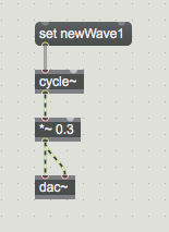
Open a new patcher and place a cycle~ object. Send it a message to read a different waveform by creating a new message set newWave1. This message tells cycle not to play the default sinusoidal waveform, computed automatically by the object, but to read a different waveform from another location, a buffer named (by me) ‘newWave1’.
The buffer~
A buffer is a piece of memory of your computer. It is a place that Max can reserve (by giving it a size and a name) for storing data to be used/accessed/read at will in the patcher. For doing so Max has the specially designed object, the buffer~ object.
So, for instance, if we decide to have a buffer of a certain size, let’s say 512 samples, we will place a new object named buffer~ and type in it a name- which should be the name we give to reserve the storage space- and a size.
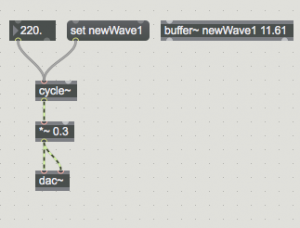
It is more precise to specify memory size in samples, but, for some reason, the buffer~ object requires it to be set in time values, in milliseconds. So let’s type in after the name 11.61, which corresponds exactly to the time computer takes to read 512 samples. The name I am adding is the name I have just used earlier to set the cycle~ object to read from: ‘newWave1’.
If we have done all correctly, the patcher should now look as in the following picture:
The cycle~ object by default will play a sinusoidal waveform at 220 Hz. When the message ‘set newWave1’ is pressed it will read instead from the buffer~ newWave1.
Writing data into a memory
The following step is to write something in the memory stored in the buffer~, to actually create some sort of wave for the oscillator to read. We can draw in the memory with the mouse.
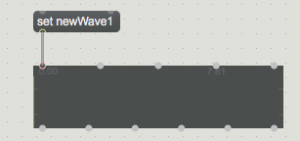
Insert in the patcher a new object named waveform~. This object is an interactive display that allows us to see the graphical representation of the data content stored in a buffer~. We need to point it to the buffer~ we want to visualise by sending it a message ‘set newWave1’, as shown in the picture below:
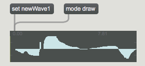
By sending the following message ‘mode draw’ to this object, we will be able to access one of its interactive features, which is to write into it. Click on ‘mode draw’ message and, with the patcher in performance mode, start clicking and scrolling within it with your mouse.
By scrolling randomly through it with the mouse, you will realise that, in the space of 11.61 milliseconds, you have drawn different amplitudes values between -1 and 1. Each amplitude value has been recorded in each of the samples available (in the time frame of 11.61 ms), that is 512 samples.
If you now run the sound through loudspeaker, and send a message to the cycle~ object to read from the new buffer~ (message: ‘set newWave1’) you might notice that the sound has passed from sinusoidal to something with slightly richer, with more harmonics (that depends much on how your drawing has come out).
Snippet of theory
As a reminder, don’t forget that with additive synthesis we have learned that different sinusoidal waveforms combined together at different amplitudes, shape (envelopes), and frequencies can create more complex tones.
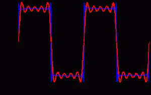
A square wave, for example, is the result of 5 different sinusoidal waveforms: the fundamental, the third, fifth, seventh, and ninth harmonic, with amplitudes respectively scaled to 1/3, 1/5, 1/7, 1/9 to the amplitude of the fundamental.
The square waveform thus composed has its particular sound and visual representation, as per picture below.
All sinusoidal waveforms are periodic. This is why we can create further sounds by reading from a buffer~. The cycle~ oscillator will read periodically through the buffer~ the waveform designed by us, producing the specific harmonics it might be composed of.
“A wavetable is a periodic function, starting and ending on zero, so it must be expressible as a sum of sines”
– Farnell, A. Designing Sound, p 277
Methods for writing data in the buffer
An alternative solution to waveform-hand-drawing is to use mathematical functions to precisely write into each of the samples the right values to create more precise shapes. To learn how to do so, you need to know three more objects: uzi, pack, and peek~.
uzi
This object performs counts in a blink of an eye. You just needs to set the number it needs to count to (always counting from 0) and it will output the whole sequence of numbers in the time of a bang. That might seem quite an un-useful thing to do, but in this case (and in many others) it will come of precious use.
pack
Pack is able to join different numbers into a list, and then trigger the list out from its output.
peek~
Peek~ is a complex object that is able to write into a buffer~, as much as we did with our mouse earlier through the waveform~ object. It needs in fact just two values: the index number (at exactly what point of the buffer length) and the value you want to write.
To draw a waveform consisting of 512 samples, we actually want to access each individual point and at each specify an amplitude value. We take an uzi object then and set it to count up till 513 (0-512). To trigger the count we just need to send uzi a bang.
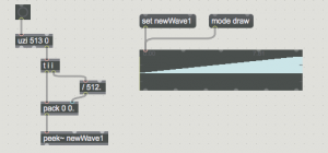
This count between 0-512 is the actual index of the buffer~. What we need to do is to calculate a waveform mathematically to obtain for each of the samples a value to draw. For example, if we take 512 and divide it by 512 we find its decimal ratio between 0 and-1. These values are 512 values ramping from 0 to 1, which actually looks as this in the next picture:
a ramp between 0 and 512.
The system to draw this ramp is realised with a combination of trigger, pack, and peek~ objects. The ramp coming from the uzi object passes first into the division object and gets stored in the right inlet of the pack object. Then it is also passed straight into the left inlet of the pack object. The trigger object is the object used to create and order these two flows of data, the one into pack object‘s right inlet and the one into pack object‘s left inlet.
The peek~ object, as described earlier, simply receives a list from the pack object containing all the values in pairs: index and amplitude value from 0 to 512th sample.
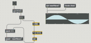
To make a better sounding waveform we need to improve the mathematical operation applied to the flush of 512 index values. A sinusoidal waveform, for example, can be created by doing the following as highlighted in yellow:
